Archiduino is a platform open-source (and open-hardware) with a modular programmable controller, 100% software compatible with Arduino Leonardo. On our CPU we have implemented some useful resources that, in the case of Arduino, would be available only by mounting one shield expansion. They are a real-time clock, an external EEPROM, an SD card (optional) and the predisposition for connection with our LCD board that also implements 4 keys.
Buy onlineCPU board

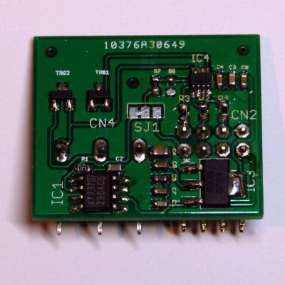
Archiduino CPU front view
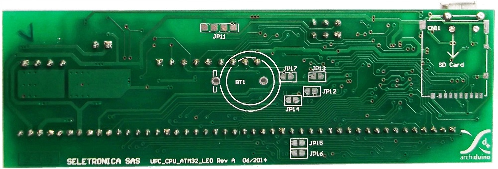
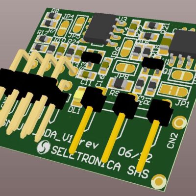
Archiduino CPU back view
Hardware resources
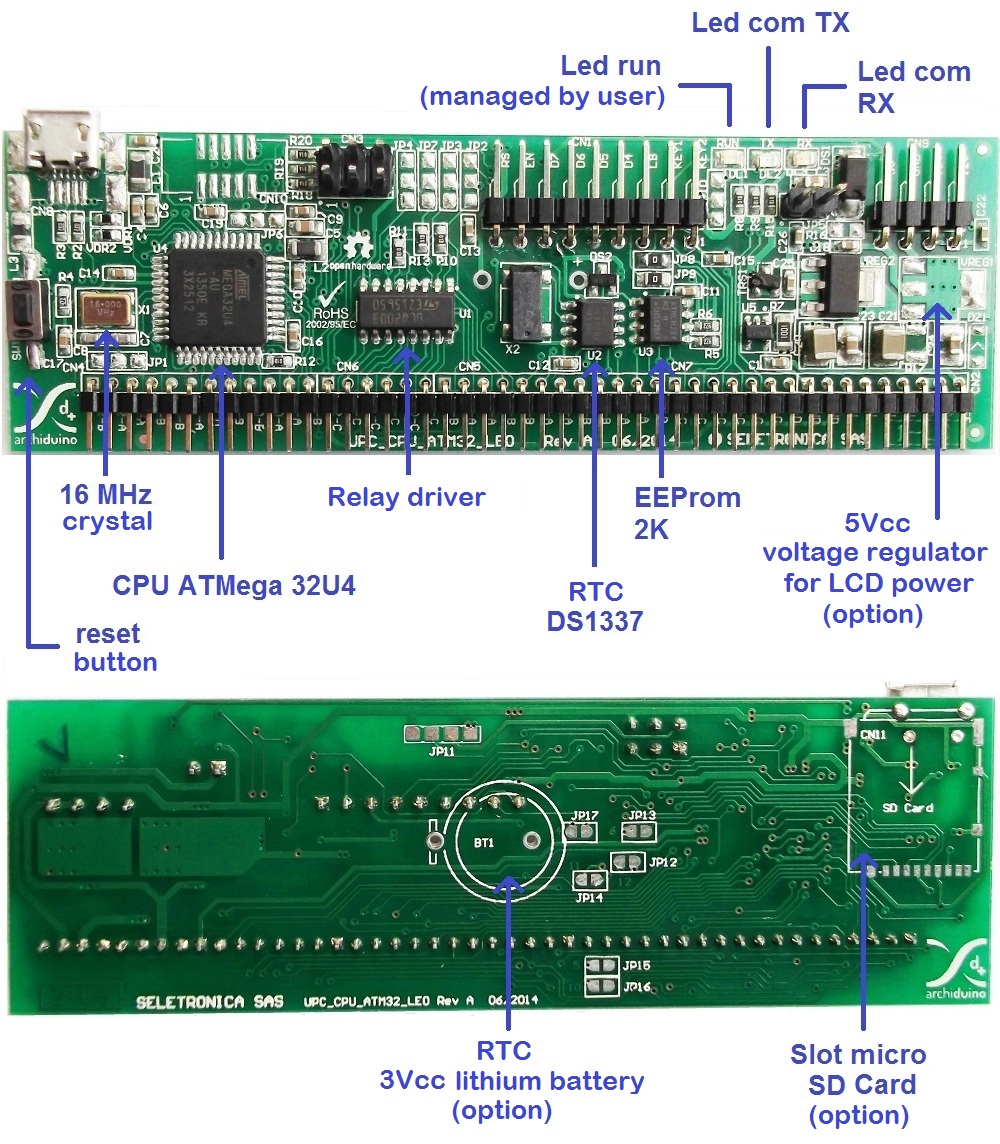
Archiduino CPU hardware resources
The hardware resources on the board (CPU clock, LCD…) use some ports of the microcontroller that can no longer be allocated to the modules. In the table below the ports of the microprocessor used by related resource are marked with the “X”.
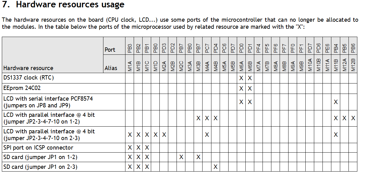
Hardware resources occupation
Connection plugs
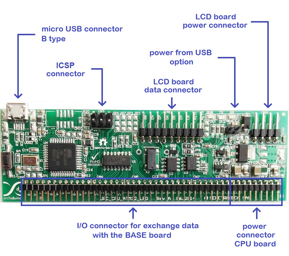
Archiduino CPU connections
Connectors pinout

Archiduino CPU external connectors pinout
[caution]
It’s important to read the instructions below. Ignoring the following recommendations can cause damage or malfunction of the device.
- Always use the CPU card inserted in the base board.
- The supply voltage is 13Vdc maximum.
- In the case in which the base is turned on out of the container, you must first verify that it is not standing on metal surfaces.
- The CPU board must be put on / removed from its connector when the base board is not powered.
- During the writing of the program you must map appropriately hardware resources based on the current configuration of the board.
[/caution]
CPU Board jumpers for LCD configuration

CPU Jumpers for LCD configuration
On the CPU board there are some jumpers (solder pads) through which you can define which ports of the microcontroller will be used to manage a particular device. Individual devices and their configurations are described below in detail.
CPU jumpers for LCD in serial I2C mode (default)
| FUNCTION | JUMPER | BRIDGE | PORT | ALIAS | ARDUINO PIN |
|---|---|---|---|---|---|
| LCD - D4 | JP2 | NO | - | ||
| LCD - D5 | JP3 | NO | - | ||
| LCD - D6 | JP4 | NO | - | ||
| LCD - D7 | JP7 | NO | - | ||
| LCD - RS (register select) | JP10 | NO | - | ||
| I2CBus SDA | JP8 | YES | PD1 (SDA) | M6B | D2 |
| I2CBus SCL | JP9 | YES | PD0 (SCL) | M6A | D3 |
CPU jumpers for LCD managed in parallel 4-bit (mode 1)
| FUNCTION | JUMPER | BRIDGE | PORT | ALIAS | ARDUINO PIN |
|---|---|---|---|---|---|
| LCD - D4 | JP2 | 1-2 | PB4 | M11B | D8 (A8) |
| LCD - D5 | JP3 | 1-2 | PB5 | M12A | D9 (A9) |
| LCD - D6 | JP4 | 1-2 | PB6 | M12B | D10 (A10) |
| LCD - D7 | JP7 | 1-2 | PB7 | M3B | D11 |
| LCD - RS (register select) | JP10 | 1-2 | PD4 | M4B | D4 (A6) |
| LCD - EN (enable) | - | - | PC7 | M4A | D13 |
| I2CBus SDA | JP8 | NO | PD1 (SDA) | M6B | D2 |
| I2CBus SCL | JP9 | NO | PD0 (SCL) | M6A | D3 |
CPU jumpers for LCD managed in parallel 4-bit (mode 2)
| FUNCTION | JUMPER | BRIDGE | PORT | ALIAS | ARDUINO PIN |
|---|---|---|---|---|---|
| LCD - D4 | JP2 | 2-3 | PB0 (SS) | M1D | |
| LCD - D5 | JP3 | 2-3 | PB1 (SPI_SCLK) | M1C | |
| LCD - D6 | JP4 | 2-3 | PB2 (SPI_MOSI) | M1B | |
| LCD - D7 | JP7 | 2-3 | PB3 (SPI_MISO) | M1A | |
| LCD - RS (register select) | JP10 | 2-3 | PD3 (TXD) | M2A | D1 |
| LCD - EN (enable) | - | - | PC7 | M4A | D13 |
| I2CBus SDA | JP8 | NO | --- | ||
| I2CBus SCL | JP9 | NO | --- |
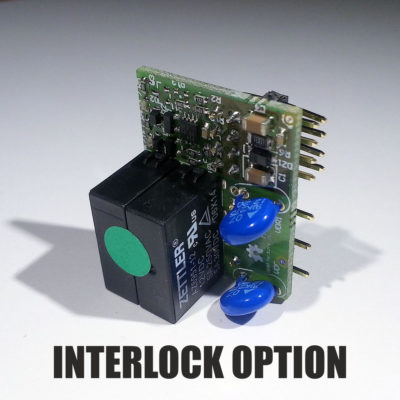
CPU Board jumpers for power relay configuration
On some slots on the base board it can be mounted a power relay (max 10A) as an alternative to the signal conditioning board. In order to control the relay, on the CPU you need to make a bridge on the jumper.
[caution]The presence of the bridge alters the signal level of the port. Thus, if the slot does not mount the power relay, the jumper MUST NOT BE PRESENT.[/caution]
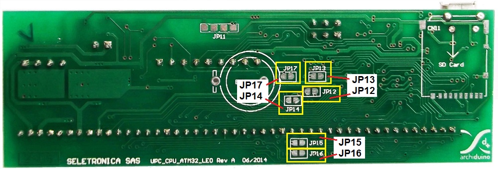
Archiduino CPU power relay jumpers
CPU jumpers for power relays configuration
| FUNCTION | RELAY SLOT | JUMPER | PORT | ALIAS | ARDUINO PIN |
|---|---|---|---|---|---|
| RELAY 4 ENABLE | 4 | JP17 | PC7 | RELE_4 | D13 |
| RELAY 5 ENABLE | 5 | JP15 | PC6 | RELE_5 | D5 |
| RELAY 6 ENABLE | 6 | JP13 | PD4 | RELE_6 | D4 (A6) |
| RELAY 10 ENABLE | 10 | JP16 | PD6 | RELE_10 | D12 (A11) |
| RELAY 11 ENABLE | 11 | JP14 | PE6 | RELE_11 | D7 |
| RELAY 12 ENABLE | 12 | JP12 | PB5 | RELE_12 | D9 (A9) |
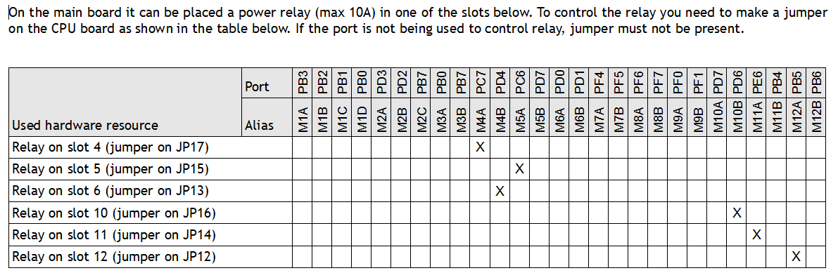
Hardware resources occupation – relays
CPU Board jumpers for SD Card (optional)
As an option, you can mount a SD Card reader. To activate the related functions, please operate as follow:
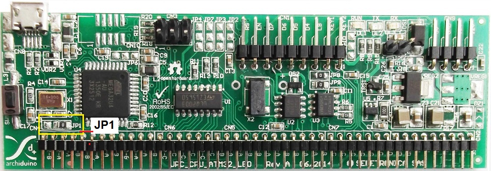
Archiduino CPU SD Card jumpers
CPU Jumpers for SD Card management
| FUNCTION | JUMPER | BRIDGE | PORT | ALIAS | ARDUINO PIN |
|---|---|---|---|---|---|
| SD CARD ENABLE - MODE 1 | JP1 | 1-2 | PB7 | M2C | D11 |
| SD CARD ENABLE - MODE 2 | JP1 | 2-3 | PD4 | M4B | D4 (A6) |
CPU Resources related to the motherboard
Archiduino Motherboard - Map of resources
| SLOT | CHANNEL | PORT | ALIAS | ARDUINO | RESOURCES |
|---|---|---|---|---|---|
| 1 | A | PB3 | M1A | Generic I/O, SPI MISO | |
| 1 | B | PB2 | M1B | Generic I/O, SPI MOSI | |
| 1 | C | PB1 | M1C | Generic I/O, SPI SCLK | |
| 1 | D | PB0 | M1D | Generic I/O, SPI SS | |
| 2 | A | PD3 | M2A | D1 | Generic I/O, serial TX (TX+ RS485) |
| 2 | B | PD2 | M2B | D0 | Generic I/O, serial RX (TX- RS485) |
| 2 | C | PB7 | M2C | D11 | Generic I/O, (serial GND, eventual TX enable RS485) |
| 3 | A | PB0 | M3A | Generic I/O | |
| 3 | B | PB7 | M3B | D11 | Generic I/O |
| 4 | A | PC7 | M4A | D13 | Generic I/O |
| 4 | B | PD4 | M4B | D4 (A6) | Generic I/O, analog input ADC8 |
| 5 | A | PC6 | M5A | D5 | Generic I/O |
| 5 | B | PD7 | M5B | D6 (A7) | Generic I/O, analog input ADC10 |
| 6 | A | PD0 | M6A | D3 | Generic I/O, I2C BUS SCL |
| 6 | B | PD1 | M6B | D2 | Generic I/O, I2C BUS SDA |
| 7 | A | PF4 | M7A | A3 | Generic I/O, analog input ADC4 |
| 7 | B | PF5 | M7B | A2 | Generic I/O, analog input ADC5 |
| 8 | A | PF6 | M8A | A1 | Generic I/O, analog input ADC6 |
| 8 | B | PF7 | M8B | A0 | Generic I/O, analog input ADC7 |
| 9 | A | PF0 | M9A | A5 | Generic I/O, analog input ADC0 |
| 9 | B | PF1 | M9B | A4 | Generic I/O, analog input ADC1 |
| 10 | A | PD7 | M10A | D6 (A7) | Generic I/O, analog input ADC10 |
| 10 | B | PD6 | M10B | D12 (A11) | Generic I/O, analog input ADC9 |
| 11 | A | PE6 | M11A | D7 | Generic I/O |
| 11 | B | PB4 | M11B | D8 (A8) | Generic I/O, analog input ADC11 |
| 12 | A | PB5 | M12A | D9 (A9) | Generic I/O, analog input ADC12 |
| 12 | B | PB6 | M12B | D10 (A10) | Generic I/O, analog input ADC13 |
Attachments
-

-
Filename : archiduino-cpu-manual_en.pdf (3 MB)
Caption : Archiduino CPU manual EN