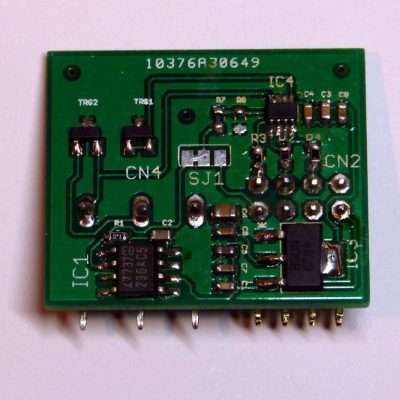
In the default configuration, the Archiduino Motherboard comes with two opto isolated inputs placed on module 12 (M12A and M12B). Besides, every module of the motherboard can be configured to run with opto isolated inputs, just soldering needed components on dedicated places.
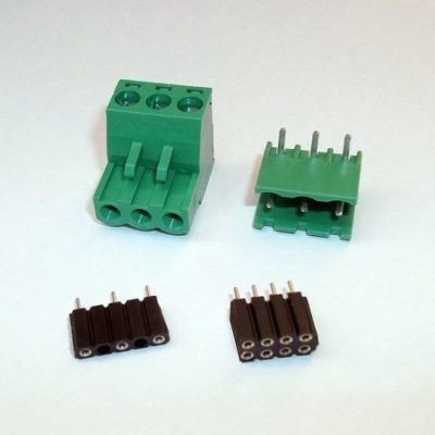
Motherboard connections
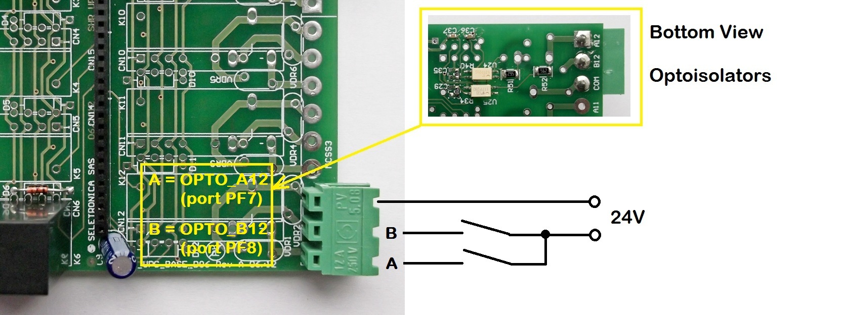
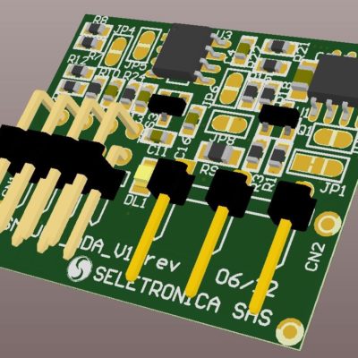
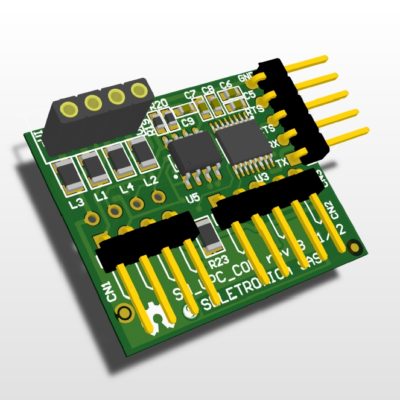
Optoisolated module – Motherboard connection
Technical specifications
- Type of input: OPTO ISOLATED DIGITAL AC/DC
- MAX Voltage: 36 Vdc / Vac
- Voltage logic state 0: 10 to 36Vdc
- Voltage logic state 1: 0 to 5Vdc
- Maximum current consumption : 5 mA
[caution] do not apply voltages input above 36VDC!![/caution]
NOTE: In case of use with a direct current voltage (Vdc) the COM channel (common) may be connected either to ground or to the positive.
Code example
/*==============================================
   ARCHIDUINO is ARDUINO Leonardo compatible
===============================================*/
/*

  PROGRAM NAME: Archiduino OPTO demo

  This program shows statuses of both opto isolated inputs on the LCD.
  The opto isolated inputs are placed on module 12 (M12A and M12B) as default.

  WARNING: DO NOT APPLY INPUT VOLTAGES ABOVE 36 VDC!!

  This software is furnished "as is", without technical support, and with no
  warranty, express or implied, as to its usefulness for any purpose.
  This example code is in the public domain.
------------------------------------------------------------------------ */

/* Includes ARCHIDUINO libraries */
#include <Archiduino.h>
#include <ArchiduinoLcd.h>
#include <pins_archiduino.h>

/* Includes ARDUINO libraries */
#include <LiquidCrystal.h>
#include <LiquidCrystal_I2C.h>
#include <Wire.h>

ArchiduinoLcd_PCF lcd;        // set the LCD address to 0x20 for a 16 chars and 2 line display

bool Opto1;                   // Input A logic state (slot 12)
bool Opto2;                   // Input B logic state (slot 12)

/* ---------------------------------------------------------------------- */

void setup() {

  delay(1000);
  lcd.init();                        // initialize the lcd
  lcd.begin(16, 2);                  // "starting" lcd and keyboard
  lcd.clear();

  //configuring pin mode
  pinMode(M12A, INPUT);
  pinMode(M12B, INPUT);

  // Print a message to the LCD.
  lcd.backlight();                  // LCD backlight ON
  lcd.print("   ARCHIDUINO   ");
  lcd.setCursor(0, 1);
  lcd.print("   OPTO  DEMO   ");
  delay(1000);
  lcd.clear();

}

/* ---------------------------------------------------------------------- */

void loop() {

  // read digital inputs (warning: with input = OFF the read status is 1)
  Opto1 = digitalRead(M12A);
  Opto2 = digitalRead(M12B);

  // outputs results on LCD
  lcd.setCursor(0,1);
  lcd.print("1 - M12A: ");
  if(!Opto1){lcd.write(255);}else{lcd.write(95);}
  lcd.setCursor(2,1);
  lcd.print("2 - M12B: ");
  if(!Opto2){lcd.write(255);}else{lcd.write(95);}

}
Attachments
-

-
Filename : base-board-input-mapping-for-optoisolated-digital-input_en.pdf (617 KB)
Caption : Base-Board input mapping for Optoisolated Digital Input_EN