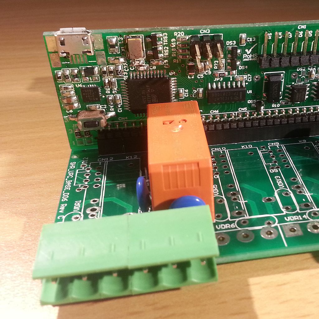
The Archiduino Base Board could host up to 12 power relays. The real number of addressable modules depends on which type of CPU Board is used in the project. Every power relay has its mandatory flyback diode paralleled with relay coil, and a couple of varistors on outputs. We’re used to use only robust, quality guaranteed relays of primary brands, as well as happens for each other Archiduino component.
Introduction
Archiduino – Power relay onboard
Archiduino power relays are tailored for maximum voltages and currents way greater than the Base Board could physically allow. Also the output connectors (the green, beloved ones) are oversized if compared to the maximum recommended voltage and current specifications.
Why this? Because Archiduino has not been engineered to do “dirty power jobs”, even if it’s designed to do a part of them (at least up to 36VAC and 4A). A great controller could have a plenty of power relays, tailored for huge current amount and with milled spark gaps for high voltages, but it couldn’t be compact. And it probably couldn’t be as affordable as a low power one.
In the other hand, in a tiny, versatile and modular controller, as Archiduino is, some power relays could be acclaimed as a useful gift, if you consider the huge amount of other features it already has, and in what small case they are stored.
Power Relays Architecture

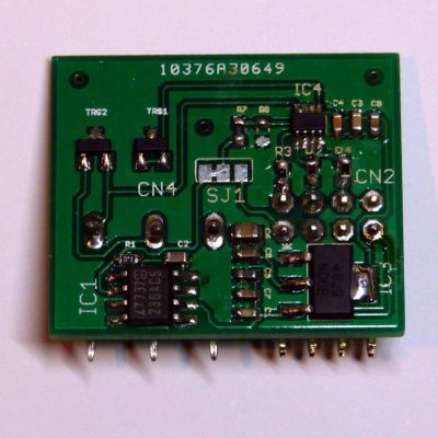
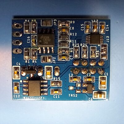
Archiduino – Power Relay + Optocoupled Feedback
Power relays are configured to work with only channel C of the selected module, freeing channels A and B for optocouplers.
This combination lets do a great job: as a matter of fact, when you drive a power relay, current flows through contact poles, if any voltage “carries” it. With optocoupled feedback you can monitor if really any voltage flows on relay’s poles. This allows user to trust the digital signal upcoming from optocouplers, avoiding situations like “Ok guys, the relay’s digital pin is ON, so why the hell motor didn’t switch on?”.
As you surely guessed, this silly example has just the purpose of lightin’up your mental bulb: what if we put Archiduino in a mission critical project and we absolutely need to monitor if a motor or a safety device are really fed (or not) with a voltage? Yes, we could do this using other inputs, but with this simple and smart solution we don’t waste a second module, saving space for other purposes.
Archiduino 1284
Archiduino 1284 allows driving up to 8 power relays. Due to the jumpers configuration, power relays should be addressed in different ways according to its position on the Base Board. Focusing on functions available on channel C only, the following table shows how to address every relay:
[supsystic-tables id=1]
Note: TPIC2810 is connected through I2C Bus at 0x64 address.
Archiduino 32
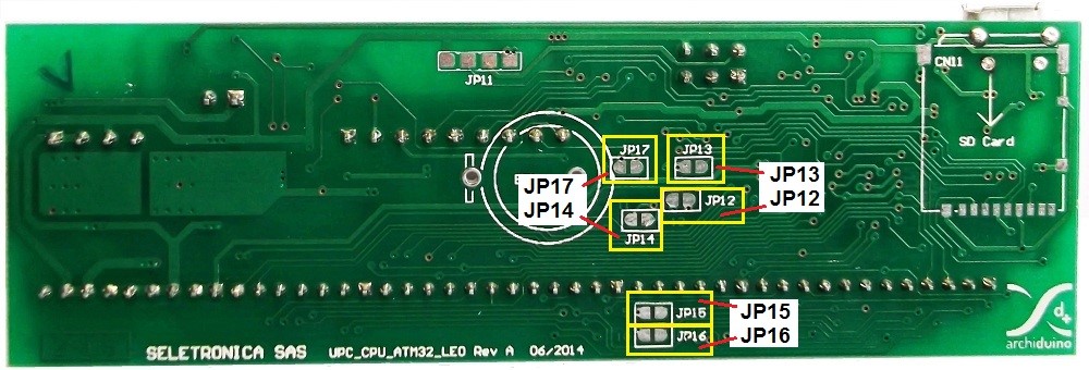
Archiduino 32 – CPU Board Bottom Side View
Archiduino 32 allows driving only 6 power relays. Power relays are driven by ULN2003 darlington driver. In order to define on which Base Board module the power relays are placed, we must set one jumper for each relay. The following table shows the correspondence between pin and relay.
| PIN | JUMPER | LOCK | Notes | |
|---|---|---|---|---|
| M1 | ||||
| M2 | ||||
| M3 | ||||
| M4 | PC7 | JP17 | M4A | |
| M5 | PC6 | JP15 | M5A | |
| M6 | PD4 | JP13 | M4B | M6 Relay also locks M4B channel |
| M7 | ||||
| M8 | ||||
| M9 | ||||
| M10 | PD6 | JP16 | M10B | |
| M11 | PE6 | JP14 | M11A | |
| M12 | PB5 | JP12 | M12A |
NOTE: as shown in the table, when a power relay is placed on M6 module, also part of M4 module is not usable.
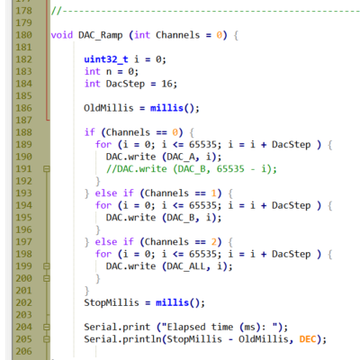
Code examples
Archiduino 1284
/*
  ARCHIDUINO by Seletronica snc - Via Degli Alpini 7 - 12020 VALGRANA (CN) - ITALY
  -----------------------------------------------------------------------------------
  Seletronica website:                 http://www.seletronica.com
  Shop and documentation repository:   http://www.archiduino.com
  -----------------------------------------------------------------------------------
  Written by: BisoTronic   ->          http://www.bisotronic.it
  Code repository on GitHub            https://github.com/bisotronic
  -----------------------------------------------------------------------------------
  This software is published "as is", without technical support, and with no
  warranty, express or implied, as to its usefulness for any purpose. Anyway, if you
  have any question or suggestion, please feel free to contact: info@bisotronic.it
  -----------------------------------------------------------------------------------
*/

// ----------------------------------- BOARD DEFINITION

#define ARCHIDUINO1284_BT = 1;		   // just for experimentation purpose

// ----------------------------------- INCLUDES

#include <RELAY1284.h>

// ----------------------------------- RELAY TPIC2810

RELAY1284 rele;


/* --------------------------------------------------------------------------*/
/* --------------------------------------------------------------------------*/


void setup() {

  rele.init();				// I2C address id set at 0x64 through library
  Serial.begin(9600);

}

/* --------------------------------------------------------------------------*/
/* --------------------------------------------------------------------------*/

void loop() {

  TestTPIC();

}

/* --------------------------------------------------------------------------*/
/* --------------------------------------------------------------------------*/

void TestTPIC() {

  Serial.println("Start Cycle");

  rele.on(REL_M5);
  delay(250);
  rele.on(REL_M6);
  delay(250);
  rele.on(REL_M7);
  delay(250);
  rele.on(REL_M8);
  delay(500);
  rele.on(REL_M9);
  delay(250);
  rele.on(REL_M10);
  delay(250);
  rele.on(REL_M11);
  delay(250);
  rele.on(REL_M12);
  delay(500);

  Serial.println("Half Cycle");

  rele.off(REL_M5);
  delay(250);
  rele.off(REL_M6);
  delay(250);
  rele.off(REL_M7);
  delay(250);
  rele.off(REL_M8);
  delay(500);
  rele.off(REL_M9);
  delay(250);
  rele.off(REL_M10);
  delay(250);
  rele.off(REL_M11);
  delay(250);
  rele.off(REL_M12);
  delay(500);

  Serial.println("Cycle complete");

}
Archiduino 32
/*
	Archiduino 32
	Power Relay Example
	------------------------------------------------------------------------------------------

	POWER RELAYS MAPPING on Archiduino32.h:

	static const uint8_t RELE_4 	 = PC7;
	static const uint8_t RELE_5 	 = PC6;
	static const uint8_t RELE_6 	 = PD4;
	static const uint8_t RELE_10 	 = PD6;
	static const uint8_t RELE_11 	 = PE6;
	static const uint8_t RELE_12 	 = PB5;

	------------------------------------------------------------------------------------------
	GENERAL NOTE: PD5 and PE2 must be used with digitalWriteEx, a custom function that
	allows the use of some resources not mapped in classical Arduino Leonardo configuration.
	For same scope we use pinModeEx instead of pinMode.

*/

int rele = RELE_11;						// RELE_11 is defined in Archiduino32.h library

void setup()
{

	pinMode(RELE_11, OUTPUT); 			// POWER RELAY (RELE_11)
	digitalWrite(RELE_11, HIGH); 		// POWER RELAY OFF

}

void loop()
{
	digitalWrite(RELE_11, HIGH); 		// POWER RELAY OFF
	delay(500);
	digitalWrite(RELE_11, LOW); 		// POWER RELAY ON
	delay(500);
}