
The Dual Channel DAC (digital to analog converter) SnipBoard in the basic version is equipped with two outputs made to drive external devices with digital signals from CPU. The maximum voltage of both outputs is set to 10 Vdc with a current of max 5 mA.
[buy]http://www.seletronica.com/en/shop/2-channels-dac-module-base-version-for-archimede-archiduino-systems/[/buy]
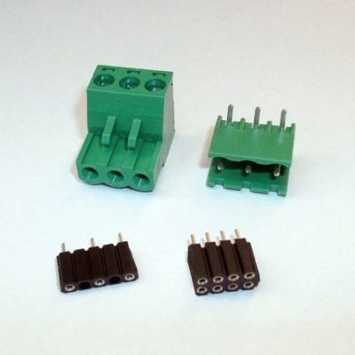
Motherboard connections

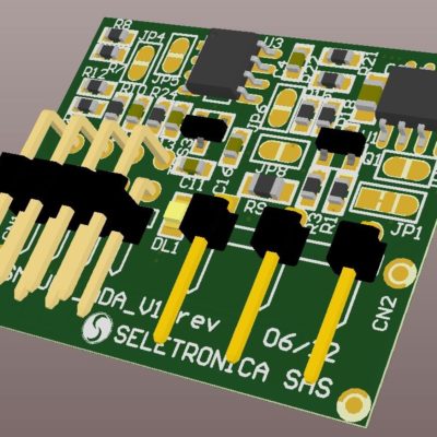
Dual channel DAC SnipCard
Technical specifications
- OUTPUT A:
- MAX Voltage: 10 Vdc
- MAX Current: 5 mA
- OUTPUT B:
- MAX Voltage: 10 Vdc
- MAX Current: 5 mA
[caution] Do not apply external voltages on the A or B outputs!!. [/caution]
Code example
/*==============================================
   ARCHIDUINO is ARDUINO Leonardo compatible
===============================================*/

/*
  In this example we activate/deactivate with a 1 second interval both relays of the
  Dual Relay SnipCard, assuming it has been mounted on socket 7.

  This software is furnished "as is", without technical support, and with no
  warranty, express or implied, as to its usefulness for any purpose.
  This example code is in the public domain.
*/

/* Includes ARCHIDUINO libraries */
#include <Archiduino.h>
#include <pins_archiduino.h>

void setup() {

  pinMode(M7A, OUTPUT);
  pinMode(M7B, OUTPUT);

}

void loop() {

  delay(1000);
  digitalWrite(M7A, LOW);    // set "ON" relay on channel A
  delay(1000);
  digitalWrite(M7A, HIGH);   // set "OFF" relay on channel A
  delay(1000);
  digitalWrite(M7B, LOW);    // set "ON" relay on channel B
  delay(1000);
  digitalWrite(M7B, HIGH);   // set "OFF" relay on channel B

}
Attachments
-

-
Filename : sm_upc_ada_v1_schematic-3.pdf (299 KB)
Caption : Dual DAC SnipCard schematic
-
-
Filename : sm_upc_ada_v1_topological-3.pdf (211 KB)
Caption : Dual DAC SnipCard topological schematic