Description
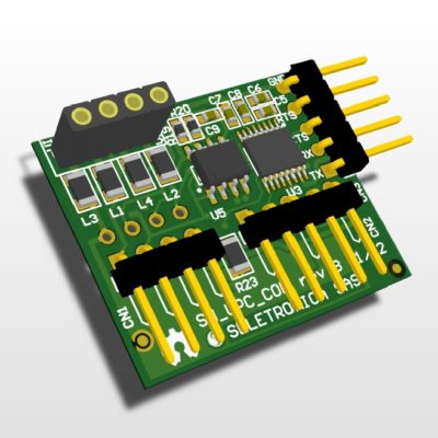
The RS-485 Serial Communication SnipCard allows to communicate in balanced digital multipoint systems with RS-485 standard. Iit can be used effectively over long distances and in electrically noisy environments. Multiple receivers may be connected to such a network in a linear, multi-drop configuration. These characteristics make such networks useful in industrial environments and similar applications.
RS-485 enables the configuration of inexpensive local networks and multidrop communications links. It offers data transmission speeds of 35 Mbit/s up to 10 m and 100 kbit/s at 1200 m. Since it uses a differential balanced line over twisted pair (like RS-422), it can span relatively large distances (up to 4,000 feet / 1,200 m). A rule of thumb is that the speed in bit/s multiplied by the length in meters should not exceed 108. Thus a 50 meter cable should not signal faster than 2 Mbit/s.
In contrast to RS-422, which has a single driver circuit which cannot be switched off, RS-485 drivers need to be put in transmit mode explicitly by asserting a signal to the driver. This allows RS-485 to implement linear bus topologies using only two wires. The equipment located along a set of RS-485 wires are interchangeably called nodes, stations or devices. (source: Wikipedia)
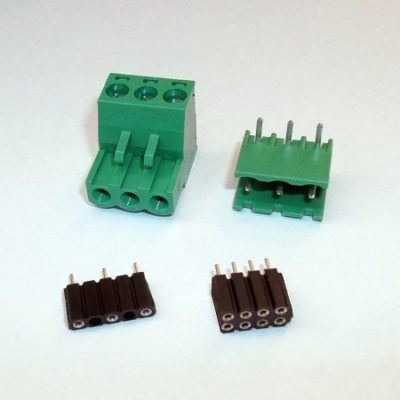
Motherboard connections
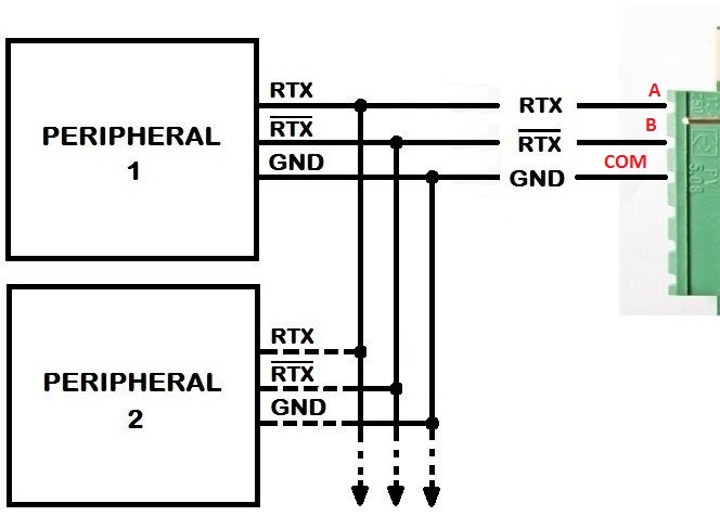
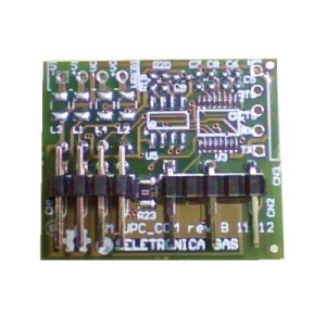
RS-485 SnipCard connections
Technical specifications
- PIN A: TX+
- PIN B: TX-
- PIN COM: GND
Code example
/* --------------------------------------------------------------------------

ARCHIDUINO RS485 DEMO

The RS485 module (SM_UPC_COM RS485 version) must be connected
on socket #2 in order to meet the TX+ and TX- pins of the CPU

Motherboard Pinout:

- Pin A: RS485 TX+
- Pin B: RS485 TX-
- COM  : RS485 GND

-------------------------------------------------------------------------- */

/* Includes ARCHIDUINO libraries */
#include <Archiduino.h>
#include <ArchiduinoLcd.h>
#include <pins_archiduino.h>

/* Includes ARDUINO libraries */
#include <LiquidCrystal.h>           // required for Archiduino LCD libraries
#include <LiquidCrystal_I2C.h>       // required for Archiduino LCD libraries
#include <Wire.h>                    // required for Archiduino LCD libraries
#include <Serial.h>

// --------------------------------------------------------------------------

ArchiduinoLcd_PCF lcd;               // set the LCD address to 0x20 for a 16 chars and 2 line display

// --------------------------------------------------------------------------

void setup() {

  delay(1000);
  lcd.init();                        // initialize the lcd
  lcd.begin(16, 2);                  // initialize lcd and keyboard
  lcd.clear();

  Serial1.begin(9600);               // initialize the serial port 1

  // Print a message to the LCD.
  lcd.backlight();                  // turn on the LCD backlight
  lcd.print("   ARCHIDUINO   ");
  lcd.setCursor(0, 1);
  lcd.print("   DEMO RS485   ");

}

// --------------------------------------------------------------------------

void loop()
{
  Serial1.println("THIS IS A RS485 TEST");
  delay(500);
}
Attachments
-

-
Filename : sm_upc_com_v1_schematic-rs485.pdf (288 KB)
Caption : RS-485 SnipCard schematic
-
-
Filename : sm_upc_com_v1_topological.pdf (174 KB)
Caption : RS-485 SnipCard topological schematic