NOPO is coming!

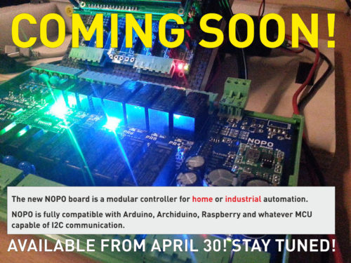
The new NOPO board is a modular controller for home or industrial automation.

LiquidCrystal_I2C.h library – for Arduino IDE 1.6.x

This library is a modified version of the H. Mario LiquidCrystal_I2C V.2.0 lib. We fixed a function in LiquidCrystal_I2C.cpp in order to allow it working with Arduino IDE 1.6.4, 1.6.5, 1.6.6, 1.6.7 and the latest 1.6.8 revision.

Download

If you want to download the whole library in a .zip file, you can do it clicking on the link below:

LiquidCrystal_I2C.h / LiquidCrystal_I2C.cpp with corrections

You also can read the following  brief explanation, it could be interesting.

Where did we gather the information?

Following the valuable informations provided by this Arduino Forum’s post we found where and how to fix the problem about an incorrect printing way on our LCD board. Same problem has been noticed from many users with as many solutions, with 95% of wrong instructions and sci-fi answers. We published our solution here because it works perfectly with our I2C PCF8574 LCD Board. We suppose that our fix is the same made by Marco Schwartz. You can optionally download Marco’s good job here.

How did we fix the problem?

Even though it looked like a vertical wall to be climbed by bare hands, mainly because of the plethora of results provided by Google to be inspected before finding any useful link, the solution was simple and simply deployable. To do this you must open LiquidCrystal.cpp with a text editor and edit this function:

inline size_t LiquidCrystal_I2C::write(uint8_t value) {
	send(value, Rs);
	return 0;
}

as follows:

inline size_t LiquidCrystal_I2C::write(uint8_t value) {
	send(value, Rs);
	return 1;
}

Et voila. A big problem with a tiny, cute solution.

Happy with this solution?

Please consider visiting our website, eventually testing our flagship product Archiduino or getting in touch with us for more information!

Any help in spreading the word about Archiduino system will be much appreciated! Thank you by Seletronica.


Sketch #1 – Blink

This simple program is a good way to do your first test on Archiduino 1284. It turns on the LED on for one second, then off for one second, repeatedly. Meanwhile it gives some infos throughout the Arduino IDE serial monitor (SHIFT+CTRL+M)

NOTES

  1. LED is a keyword embedded in pins_arduino.h, the default pins assignment library that is loaded when you choose Archiduino1284 board on Arduino IDE. If you feel more comfortable with other definitions, you may use instead:
    – PD6
    – D9 (or simply 9)
  2. This firmware works ONLY with Arduino IDE 1.6.2.
  3. Logical state of the LED is inverted, so if you set it as LOW, the LED lights on.

Code

/*
// ===============================================
//   ARCHIDUINO 1284 Test Sketch
// ===============================================

//----------------------------------------------------------------------------------
//----------------------------------------------------------------------------------

  Sketch n.:    1
  Sketch title: Blink

  This sketch turns on the LED on for one second, then off for one second, repeatedly. Meanwhile
  it gives some infos throughout the serial monitor (SHIFT+CTRL+M)
  
  NOTES:
  LED is a keyword embedded in pins_arduino.h, the default pins assignment library  
  which is loaded when you choose Archiduino1284 board on Arduino IDE.
  You may use instead:
  - PD6
  - D9 (or simply 9)
  
  Logical state of the LED is inverted, so if you set it as LOW, the LED lights on.

//----------------------------------------------------------------------------------
//----------------------------------------------------------------------------------

  This software is published "as is", without technical support, and with no 
  warranty, express or implied, as to its usefulness for any purpose.  
  This example code is in the public domain.

//----------------------------------------------------------------------------------
//----------------------------------------------------------------------------------
*/


//----------------------------------------------------------------------------------
//----------------------------------------------------------------------------------

void setup() {
  
  pinMode(LED, OUTPUT);   // initializing the digital pin as an output.
  Serial.begin(9600);     // initializing the serial port 0
  
}


//----------------------------------------------------------------------------------
//----------------------------------------------------------------------------------

void loop() {
  
  digitalWrite(LED, LOW);     // turns the LED on 
  Serial.println("LOW");      // gives some info throughout the serial monitor
  delay(1000);                // waits for 1000 ms
  digitalWrite(LED, HIGH);    // turns the LED off
  Serial.println("HIGH");     // gives some info throughout the serial monitor
  delay(1000);                // waits for 1000 ms
  
}


As you can see, we made some restyling to the website. We are trying to rearrange the whole categorization of posts and various items.

Furthermore, we also created a shop area, so if you want to buy Archiduino you could do it without going to the previous e-commerce website.

At the moment the shop is pretty empty but we consider to “fix and fill” it as soon as possible. If you are thinking to buy something, you can do it here: www.seletronica.com

We’re also working to new documentation, new manuals, new experiments, new code, new libraries and… new SnipCards.

Archiduino is alive and kicking! Stay tuned!


In this video we show you how much easy is the assembly of Archiduino with a couple of SnipCards. The video has no commentary but below we list the points where – in our humble opinion – a little explanation could be helpful.

0:20: this is an ADA SnipCard being mounted on slot M7; on the standard base board there’s always a power relay on slot M11, so if the board is placed in front of you from relay side you can count – from left to right – M12 / M11 / M10 / M9 / M8 / M7. A good way to identify the right side of the base board is to look at the power connector (3 pins): it’s always at the left of the M1 slot.

0:27: SnipCard UIO mounted on M8

0:32: the chip on the SnipCard is an ST3232, so the SnipCard is a COM RS232. It must go in the slot M2, the “Serial1” slot (unless you use some SoftSerial library).

1:03: if you expect to use Archiduino enclosed in the DIN Box, you must put it into there WITHOUT the CPU. If not, the base board with the CPU won’t enter in the box. So, first put the base board with SnipCards, then fit the CPU board on the socket.

1:11: the board falls into the space between two small edges, look at how to check the best fit.

1:18: the CPU male connector has a 2 mm pitch, be careful when inserting in the female connector on the base board. Look at the right orientation: Archiduino is in front of you with the two LEDs at your right hand, and the CPU has the Atmel processor in front of you with the 2 mm pitch connector set downward. The insertion should be done keeping the CPU board slightly askew, beacuse the two flanks are very close to the ensemble in order to minimize the gap and mechanical stress.

1:40: when the extremities of the 2 mm pins are just in place on correspondent holes of the female connector, you should apply with both thumbs a gentle pressure on the CPU board perpendicularly to the base board.

2:01: take a look at the LCD connector. There’s no chance to put it in the wrong place.

2:32: placing the LCD looks tricky, but it’s easier than you think (just an “uncut” hitch).


With this post we open the new category “Test files”, which is a sort of repository for testing and experimenting with Archiduino. Every test file contains the results of real experiments, not just theory. We hope this will be of any help to the growing family of Archiduino (and – why not? – Arduino) users. So, let’s start! (more…)


After a challenging server migration the Archiduino website is finally back. We apologize for the unintentional blackout. As soon as possible we will update the Application section with new “test files”, so… stay tuned!